 NOTE: The input data must be in units of mm. for the distances reported
to be meaningful - there is no way to enforce this with any of the 3d surface
data formats used.
NOTE: The input data must be in units of mm. for the distances reported
to be meaningful - there is no way to enforce this with any of the 3d surface
data formats used.
NOTE: The input data must be in units of mm. for the distances reported
to be meaningful - there is no way to enforce this with any of the 3d surface
data formats used.
Markers can be placed on any visible surface at any orientation. Accuracy
of placement is improved if the image is rendered at high resolution by
zooming the region of interest with the [resize] option. Maximising the
window does NOT improve measurement accuracy.
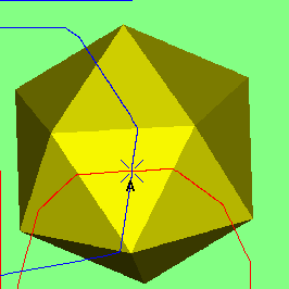
Markers are placed by clicking the left mouse button over the object. The marker can be dragged around on the surface until the button is released (fine adjustment of marker position with the cursor keys is also possible if the move marker mode is selected - press enter to fix the new position). Two styles of interaction are supported: the first shows a simple cross where the marker will be placed, the other also shows the surface curvature by showing horizontal (red) and vertical (blue) profiles across the surface. These can assist in the correct placement of markers.
When placing a marker, a blue cross is displayed, indicating that the marker is ON the surface. If it is more than the size of a data pixel away from the displayed surface the colour of the cross is changed to green. Markers added using the Add Marker at XYZ menu entry in the Orient menu are very likely to be displayed in green as they are unlikely to be placed exactly on a surface.
A Measurements window is displayed:-
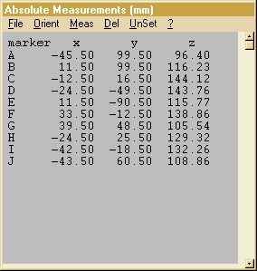 The
window initially displays x, y, z co-ordinates of the markers in absolute
measurements mode; where x=0, y=0, z=0 is at the centre of the screen
in the initial orientation. Units are mm (provided that the input data
file contains mm resolution data!).These co-ordinates are viewpoint independent
and will not change if the view is rotated or shifted. If the screen
measurements mode in the Orient menu is checked, then co-ordinates
are displayed in the frame of reference of the current view with 0,0,0
at the centre of rotation. These co-ordinates will change with viewpoint.
When saving a data file it can be written in
either the original coordinate space (as loaded) or in the current screen
co-ordinate space. The preferred mode is selected in the mode
menu. If the user defined measurements mode in the Orient
menu is checked, then co-ordinates can be displayed in a frame
of reference defined by the user. These co-ordinates will not change
with viewpoint. If a reference point is selected,
the display changes to show distances from each marker to the reference
marker. Solid angles (in degrees) and distances
to a reference plane can also be displayed.
The
window initially displays x, y, z co-ordinates of the markers in absolute
measurements mode; where x=0, y=0, z=0 is at the centre of the screen
in the initial orientation. Units are mm (provided that the input data
file contains mm resolution data!).These co-ordinates are viewpoint independent
and will not change if the view is rotated or shifted. If the screen
measurements mode in the Orient menu is checked, then co-ordinates
are displayed in the frame of reference of the current view with 0,0,0
at the centre of rotation. These co-ordinates will change with viewpoint.
When saving a data file it can be written in
either the original coordinate space (as loaded) or in the current screen
co-ordinate space. The preferred mode is selected in the mode
menu. If the user defined measurements mode in the Orient
menu is checked, then co-ordinates can be displayed in a frame
of reference defined by the user. These co-ordinates will not change
with viewpoint. If a reference point is selected,
the display changes to show distances from each marker to the reference
marker. Solid angles (in degrees) and distances
to a reference plane can also be displayed.
Clicking on the line of text for a marker in the measurements window will
cause the profiles for that marker to be displayed. Left clicking on a
marker first brings up brings up a selection menu (as shown in the sample
window above, left) which provides operations on the chosen marker
:
The measurement window menu has the following entries:
| File | Load Markers from file | Reads marker locations from a .LAN file which has been previously saved. Any markers already present will be deleted. |
| Add Markers from file | Reads marker locations from a .LAN file which has been previously saved. If markers are already present, the loaded markers will be added at the end of the sequence. The resulting identifying tags will, therefore, be different from those at the time they were saved. | |
| Save Markers to file | Writes marker locations to a .LAN file which can be re-loaded later or writes the window text to a .TXT file for export. | |
| Markers to clipboard | Writes marker locations in text format to the windows system clipboard. They can be pasted from the clipboard into other software packages. | |
| Orient | absolute measurements | When checked (default) x,y,z co-ordinates are displayed in data space
with 0,0,0 at the left (x), front (y) , top (z) corner of the data space
in the initial view. In the conventional CT slice view (from below) x is
across the slice (left to right), y is down the slice (top to bottom),
z is out through the stack of slices (top slice to bottom slice). |
| screen measurements | When checked x,y,z co-ordinates are displayed relative to the current view with 0,0,0 at the centre of rotation (and at the centre of the window).The X-axis is horizontal with negative values to the left. The Y-axis is vertical with negative values at the top. The Z-axis is out of the screen with negative values at the back. Rotating or shifting the viewpoint will change the co-ordinates displayed for a marker. | |
| user defined measurements | When checked x,y,z co-ordinates are displayed in a user definable space. This mode must be selected in order to define the frame of reference. | |
| Ref. point to centre | Shifts the view to put the reference point marker at the centre of rotation | |
| Ref. line vertical | Rotates the view so that the reference line appears vertical on the screen, but is not necessarily parallel to it. | |
| Ref. line horizontal | Rotates the view so that the reference line appears horizontal on the screen, but is not necessarily parallel to it. | |
| Ref. line in screen | Rotates the view so that the reference line becomes parallel to the screen. | |
| Ref. plane vertical | Rotates the view so that the reference plane appears vertical on the screen. | |
| Ref. plane horizontal | Rotates the view so that the reference plane appears horizontal on the screen. | |
| Ref. plane in screen | Rotates the view to put the reference plane parallel to the screen. | |
| Meas | Radius of curvature | 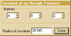 A
dialog box is displayed allowing the user to select 3 markers. The radius
of curvature of a circular arc passing through the 3 markers is calculated. A
dialog box is displayed allowing the user to select 3 markers. The radius
of curvature of a circular arc passing through the 3 markers is calculated.
|
| Angle between lines | 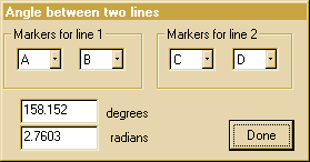 A
dialog box is displayed allowing the user to select 4 markers. The angle
between the two selected lines is calculated. Selecting A-B and A-B again
will give an angle of 0 degrees/radians. Swapping the order of points on
one line (A-B and B-A) will give an angle of 180 degrees. A
dialog box is displayed allowing the user to select 4 markers. The angle
between the two selected lines is calculated. Selecting A-B and A-B again
will give an angle of 0 degrees/radians. Swapping the order of points on
one line (A-B and B-A) will give an angle of 180 degrees. |
|
| Angle between planes | 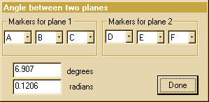 A
dialog box is displayed allowing the user to select 6 markers. The angle
between the two selected planes is calculated. Selecting A-B-C and A-B-C
again will give an angle of 0 degrees/radians. Swapping the order of points
on one triangle (A-B-C and A-C-B) will give an angle of 180 degrees. A
dialog box is displayed allowing the user to select 6 markers. The angle
between the two selected planes is calculated. Selecting A-B-C and A-B-C
again will give an angle of 0 degrees/radians. Swapping the order of points
on one triangle (A-B-C and A-C-B) will give an angle of 180 degrees. |
|
| Add Marker at XYZ | This allows the user to add a marker at an arbitrary x,y,z position in the current frame of reference. | |
| Add Marker at vertex centre | This calculates the mean position of all the vertices in the data set and adds a marker at this location. | |
| Add Marker at surface centre | This performs a similar action to the above option but weights the calculation with the area of each surface triangle. If the surface of the object is unevenly sampled, this will give a better approximation of the object centre. | |
| Add mid-point marker | A dialog box is displayed allowing the user to select 2 markers. Pressing ok will add a new marker at the mid-point between the chosen markers. | |
| Distances to nearest surface | Lists the distance of each marker from the nearest surface of the object.. | |
| Move markers to nearest surface | If any markers are not on a surface, this option finds the nearest surface and moves the marker there. | |
| Resequence markers |  Markers are
automatically labelled in the order that they are created. This dialog
enables re-arranging the label order. A pair of markers can be exchanged
with the swap markers option (swap b,d converts a,b,c,d,e,f, to:
a,d,c,b,e,f,). The shift marker option moves a single marker to a new position
but all the markers in the intervening space will shift one step in the
opposite direction (shift a,e converts a,b,c,d,e,f, to b,c,d,e,a,f.). Markers are
automatically labelled in the order that they are created. This dialog
enables re-arranging the label order. A pair of markers can be exchanged
with the swap markers option (swap b,d converts a,b,c,d,e,f, to:
a,d,c,b,e,f,). The shift marker option moves a single marker to a new position
but all the markers in the intervening space will shift one step in the
opposite direction (shift a,e converts a,b,c,d,e,f, to b,c,d,e,a,f.). |
|
| Fit LSQ line to markers | 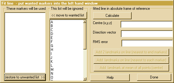 This option allows the user to fit the best (Least Square error) line through the set of points selected in the left hand window of the dialog box. The RMS error of the points to the line is reported. After Calculation, extra landmarks can be added on this line using the buttons on the right side of the dialog box or, by double clicking on any marker in the selection windows, a new marker can be added on the line at the nearest point to the clicked marker. Individual distances, from each point to the fitted line, are diplayed in the selection windows, adjacent to each marker name, after fitting. There is also an extra option to remove the worst fitting point from the list and re-calculate. |
|
| Fit LSQ plane to markers | This is similar to the option above but fits the best plane to the selected set of points. After the plane has been defined, double clicking on any marker in the selection windows will add a new marker on the plane at the nearest point to the clicked marker. Individual distances, from each point to the fitted plane, are diplayed in the selection windows, adjacent to each marker name, after fitting.There is also an extra option to remove the worst fitting point from the list and re-calculate. | |
| Fit LSQ sphere to markers | This is similar to the option above but fits the best sphere to the selected set of points. After the sphere has been defined, double clicking on any marker in the selection windows will add a new marker on the sphere at the nearest point to the clicked marker. Individual distances, from each point to the fitted sphere, are diplayed in the selection windows, adjacent to each marker name, after fitting.There is also an extra option to remove the worst fitting point from the list and re-calculate. | |
| Fit LSQ circle to markers | This is similar to the option above but fits the best circle to the selected set of points. This has to be a two stage process. First a best fit plane to the points is found. Temporary copies of the selected points are moved into this plane before finding the best fit circle. Individual distances, from each point to fitted circle, are diplayed in the selection windows, adjacent to each marker name, after fitting.There is also an extra option to remove the worst fitting point from the list and re-calculate. | |
| Length of polyline | 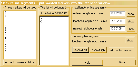
This option has two main functions: measurement and editing. The measurement function calculates the length of a number of straight line segments between markers. The first measure, ordered length joins all of the chosen markers in their alphabetic order. Click on the show button to see the measured line segments. The loopback measurement also adds in the line segment from the last marker to the first marker. The nearest neighbour option will not necessarily use all of the selected makers. Use the show button to see the path actually used. Nearest neighbour finds the pair of markers which are farthest apart and joins lines between these and their nearest neighbours, using the markers in any appropriate order. The cutting functions allow part of the surface to be discarded. A closed loop, defined by a sequence of makers, is used as a segmentation boundary. All parts of the surface on one side of the line can be deleted. The left or right side of the line is discarded as defined by looking along the line in the order of the markers. The contour must be closed and must not cross or meet the edge of the object surface. This will only work correctly if the surface is composed of correctly joined trianglar patches and no duplicated vertices. If an STL file has been loaded it must be "condensed" before any editing. |
|
| Paint round markers | 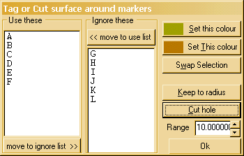 This
allows selected markers to be used to tag a region of the surface around
each selected marker. This is equivalent to painting these regions in the
edit mode. This
allows selected markers to be used to tag a region of the surface around
each selected marker. This is equivalent to painting these regions in the
edit mode.
The selected markers can also be used to cut holes in the surface or trim to a radius. When trimming, the boolean union of all regions is discarded so, if two markers are selected and are separated by more than the range, the entire object will be deleted! |
|
| AllDel | Clears the entire marker list | |
| UnSet | Clears plane, line & point attributes (one per click) | |
| ? | This Help | |
User Defined Frame of Reference
If the user defined measurements option is checked, then right
clicking on a marker in the measurements window will bring up a different
selection window. The marker which was selected is indicated in the top
bar of the window. This is the marker that will be used if a marker dependent
button is pressed 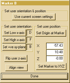 This
window allows the user to define their own frame of reference for the co-ordinates
displayed by the marker window. It has a number of different controls for
modifying the frame of reference.
This
window allows the user to define their own frame of reference for the co-ordinates
displayed by the marker window. It has a number of different controls for
modifying the frame of reference.
The first option, Set user orientation & position, sets a frame of reference by copying the current screen settings. This re-defines both orientation and the position of the origin.
The second option, set user orientation, allows the definition of orientation by using two markers to define the x-axis direction and a third to define a positive y value in the x-y plane. Clicking on one of the buttons selects the current marker as the new definition of this component of the frame of reference.The new frame of reference is only established when all three reference markers have been selected. After this, picking any one new reference marker will immediately establish a new frame of reference. Changing the orientation causes a rotation about the currently defined origin which will remain at 0,0,0. If one of these reference markers is moved to a new location in the data space, the user frame of reference will change while the marker is moving.
The user position can be separately defined at any one marker, either by setting the origin (x=0;y=0,z=0) at the chosen marker or by setting user defined values at the marker. This shifts the frame of reference without any rotation of the axes.
The user can also define the sense of the z-axis by flipping values in this axis. This will flip about z=0 so if the set XYZ at Marker option is used, care should be taken to ensure that the intended frame of reference is established.
The Align View button rotates the view of the data set so that the user defined frame of reference is rotationally aligned with the screen frame of reference. The X-axis is horizontal with negative values to the left. The Y-axis is vertical with negative values at the bottom. The Z-axis is out of the screen with negative values at the back (unless Flip z-axis has been used to invert the z-axis). The origin is not shifted to the centre of screen.
Saving data in the user defined frame of reference
To save a data set in the user defined co-ordinates, it is first necessary to add a marker at x=0,y=0,z=0 in the user frame of reference. Then use Align View to rotate the data into the desired screen orientation followed by put to centre on the marker that defines the origin to offset the data into the correct position. Then save the data set, making sure that the Save at current view option is checked in the mode menu