3D Editing
 This mode
is used for segmenting the surface into two categories either for deleting
unwanted bits of surface or for performing certain operations on only part
of the surface such as area measurement
and surface registration. The painted marks
are remembered so that repeated painting from different viewpoints can
be used to paint all round an object surface before using the segmentation.
The editing pattern can be saved to disk file (from the file
menu) for later re-use .Please note that this segmentation operates
by tagging individual surface triangles. There are two modes of painting,
defined by the state of the Visible surface only check box. The
default mode (checked) is set every time edit mode is selected. In this
mode only the visible surface is marked. If a triangle is too small to
be marked it cannot be tagged - enlarging the object (by zooming
in) generally solves this marking problem. If Visible surface only
is unchecked, then marking is applied to ALL triangles at any distance
into the screen within the marked area. This mode is useful for removing
large regions of data. Painting is unreliable if the main image window
has been made smaller than the standard size (see StdSize in file
menu).
This mode
is used for segmenting the surface into two categories either for deleting
unwanted bits of surface or for performing certain operations on only part
of the surface such as area measurement
and surface registration. The painted marks
are remembered so that repeated painting from different viewpoints can
be used to paint all round an object surface before using the segmentation.
The editing pattern can be saved to disk file (from the file
menu) for later re-use .Please note that this segmentation operates
by tagging individual surface triangles. There are two modes of painting,
defined by the state of the Visible surface only check box. The
default mode (checked) is set every time edit mode is selected. In this
mode only the visible surface is marked. If a triangle is too small to
be marked it cannot be tagged - enlarging the object (by zooming
in) generally solves this marking problem. If Visible surface only
is unchecked, then marking is applied to ALL triangles at any distance
into the screen within the marked area. This mode is useful for removing
large regions of data. Painting is unreliable if the main image window
has been made smaller than the standard size (see StdSize in file
menu).
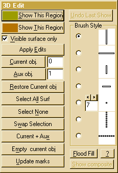
Press the right mouse button in the main window and drag to unselect
a region of the image in the aux colour (this colour can be modified in
the colour selection menu). Click and drag with
the left mouse button to restore the normal colour. Once the regions are
painted satisfactorily, two buttons in the edit menu (Show This Region)
allow the choice of showing either coloured region. Apply Edits
will irreversibly remove any unshown parts of the object.. If the
edit pattern is saved after using Apply Edits then the pattern canot
be loaded onto the original data - the edited data should also be saved
to disk (as an obj or stl file) if subsequent re-use is intended.The Undo
Last Show button reverses the effect of the last Show This Region
click. The Restore Current Obj. button reverses the effect of all
Show This Region clicks unless Apply Edits has been used
which cannot be reversed. The Select All Surf button causes the
whole object surface to be marked in the normal colour. The Select None
button causes the whole object surface to be marked in the aux colour.
The Swap selection button reverses the marking pattern.
Different objects can be moved independently within the view
control menu to allow comparison of surfaces or to determine the relative
positions of two objects prior to them being combined into a new object.
It displays an edit control window and selects a brush for painting on
the image.
A total of eight objects (numbered 0 to 7) may be loaded from files
or created by combining two existing objects (using the current+aux
button). Multiple copies of the same file can be loaded. At any one time,
two of these objects may be tagged as having special status (Current Obj
& Aux Obj.).The Current object is the one, from the available set of
objects, which is being examined or operated upon. The Aux object is the
one used in operations involving a second object (registration,
combination, surface difference mapping).
The buttons Current obj. and Aux. obj. display a list
of objects to allow reselection. 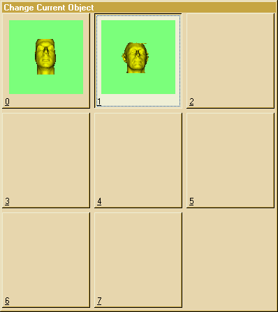 The
highlighted image indicates the existing state of the system. Clicking
on any image exits the list, selecting the chosen object. If an object
selected to be the new "current obj" is already in the "Aux
obj" state, the current and aux tags are automatically swapped.
The
highlighted image indicates the existing state of the system. Clicking
on any image exits the list, selecting the chosen object. If an object
selected to be the new "current obj" is already in the "Aux
obj" state, the current and aux tags are automatically swapped.
The menu also contains a selection of different brush styles for painting
regions. The first four brushes are the same size and shape as the white
part of the cursor, the last two paint a stripe the full height or the
full width of the screen respectively. The fifth brush is an adjustable
sized spot which can be varied in size from 1 to 50 pixels. If a region
is outlined with a brush, the patch in the middle can be painted in by
clicking on the flood fill button and then clicking, with either
the left or right button as appropriate, inside the region to be filled.
Only a region with a closed boundary will be filled. Clicking outside the
main window aborts the flood fill mode.
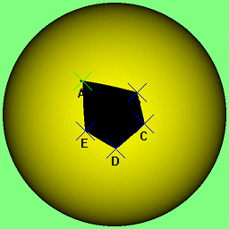
Marker Based Editing
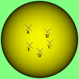
5 markers on a sphere
|
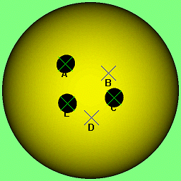
Holes cut at markers A,C,E
|
Discard to right of contour
|
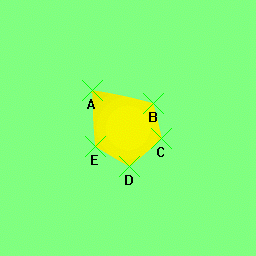
Discard to left of contour
|
There are some extra editing functions, based on the use of landmarks,
which can be found in the measurement menu.
The object can be trimmed along a closed loop boundary in the polyline
option. Holes can be cut with the paint round markers
option. These editing functions will alter the triangles on the boundary
of the cut to produce a clean edge.
Back to index
©2008 Robin Richards, All rights reserved.